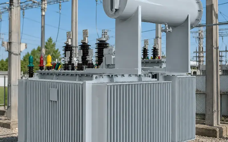
How to test a transformer on site before energising
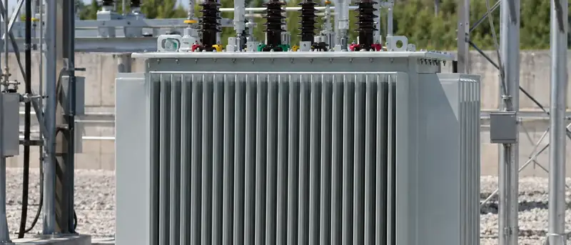
To test a transformer on site, the commissioning team first inspects it for transport damage, then measures insulation resistance, turns ratio and vector group, winding resistance and, for oil-filled units, oil breakdown voltage and moisture. They then check protection devices and accessories and compare every result with the factory test report before the transformer is energised for the first time.
Key takeaways
- Site tests do not repeat the factory type tests. Their purpose is to prove that nothing changed during transport, storage and installation, so the factory routine test report is the reference for every result.
- The core set of field tests is insulation resistance, ratio and vector group, winding resistance, excitation current and, for liquid-filled units, oil tests. Large units add SFRA and dissipation factor.
- Record temperature with every measurement. Insulation resistance and winding resistance both change strongly with temperature.
- Protection and accessories (gas relay, pressure relief, temperature indicators, tap changer, CTs) must be function-tested, not just inspected.
Why test a transformer on site if it passed factory tests?
A transformer leaves the factory after a full set of routine tests, described in our article on transformer routine tests before shipment. Between that test bay and your foundation, it is lifted, shipped, trucked, possibly stored for months and then reassembled. Shocks can shift a core or loosen a lead; a damaged gasket can let in moisture; a bushing can crack; a tap changer can be left on the wrong position.
Field tests by the site team catch these problems while they are still cheap to fix. They also create a baseline set of site readings for future maintenance. IEEE C57.152 is the main guide for diagnostic field testing of liquid-filled transformers, and most utility commissioning procedures follow a similar list.
How do you test a transformer on site, and what comes first?
Start with a physical inspection on arrival, before the unit is moved to its final position:
- Impact recorder. If the transformer travelled with a shock recorder, read it and compare peaks against the limits agreed in the contract. Our guide on shipping transformers covers why recorders are worth specifying.
- Tank, radiators and welds. Look for dents, oil stains and damaged paint.
- Pressure or oil level. Units shipped filled with dry gas should still show positive pressure; oil-filled units should show the correct level.
- Bushings and terminals. Check for chips, cracks and loose connections.
- Accessories. Count them against the packing list: gas relay, pressure relief device, temperature indicators, breather, valves, cable boxes.
- Nameplate. Confirm rating, voltages, vector group and serial number against the approved drawing and the test report.
Record everything with photographs. Claims for transport damage depend on evidence collected at delivery.
Which tests make up transformer testing at commissioning?
The table below lists the usual site tests, what each reveals and what to compare it with.
| Test | Typical instrument | What it detects | Compare with |
|---|---|---|---|
| Insulation resistance and polarisation index | Insulation resistance tester (DC) | Moisture, contamination, insulation damage | Factory values at similar temperature, trend between windings |
| Turns ratio and vector group | Transformer turns ratio tester | Wrong tap, shorted turns, wrong connection | Nameplate ratio on every tap, factory report |
| Winding resistance | DC winding resistance meter | Loose joints, poor tap-changer contacts, broken strands | Factory values corrected to the same temperature, phase-to-phase balance |
| Excitation current | Low-voltage AC test set | Core damage, shorted turns, residual magnetism | Phase pattern and factory or first-site values |
| Core and frame insulation | Insulation resistance tester at low DC voltage | Unintended second core earth | Factory value |
| Oil breakdown voltage | Oil dielectric test set | Water and particles in the oil | Limits in IEC 60422 or the supplier's specification |
| Oil moisture and DGA baseline | Laboratory analysis | Wet insulation; baseline for future gas analysis | Supplier's values for new oil |
| SFRA (if a factory trace exists) | Sweep frequency response analyser | Winding movement or core shift in transit | Factory trace |
| CT ratio and polarity | CT test set or primary injection | Wiring errors in protection and metering | Drawings and relay settings |
Insulation resistance test
The insulation resistance test applies a DC voltage between windings and between each winding and earth, then reads the leakage resistance. Common test voltages are 2.5 kV or 5 kV DC for medium- and high-voltage windings and 500 V or 1 kV DC for low-voltage windings, never above what the winding insulation is designed for. Test HV to LV and earth, LV to HV and earth, and HV to LV.
- Isolate the transformer, earth all terminals and disconnect surge arresters, cables and neutral links where practical.
- Short together all terminals of each winding.
- Apply the test voltage and record readings at 1 minute and 10 minutes. The ratio of the 10-minute to the 1-minute reading is the polarisation index.
- Record oil or winding temperature and ambient humidity.
- Discharge each winding to earth for at least as long as the test lasted.
Insulation resistance falls sharply as temperature rises, so only compare values at similar temperatures or after temperature correction. A value well below the factory figure, or a low polarisation index, points to moisture and must be investigated before energising.
Ratio test and vector group
A turns ratio tester applies a low AC voltage to the HV winding and measures the LV voltage on every phase and every tap position. IEC 60076-1 and IEEE C57.12.00 both use ±0.5% of the declared ratio as the basic tolerance at the principal tap (IEC can be tighter for units with low impedance), and the measured ratios should also match the factory report closely. The same instrument confirms phase displacement, so you can see that a Dyn11 unit really is Dyn11 before it is paralleled with others. Our article on vector groups such as Dyn11 and Yyn0 explains why this matters.
Finish the test with the tap changer on the position required by the network study, and record it. Tap changer types and settings are covered in on-load vs off-circuit tap changers.
Winding resistance
A DC current is injected through each winding and the voltage drop measured once the reading is stable. Measure every phase and, on the tapped winding, every tap. Correct results to the factory reference temperature before comparing. Unexplained differences of more than a few per cent between phases, or between site and factory values, point to a poor joint or contact.
The DC test leaves the core magnetised. Demagnetise it afterwards, or do the excitation current test before winding resistance, because residual magnetism increases inrush current at energisation and distorts excitation readings.
Oil tests
For oil-filled transformers with sampling valves, take a sample from the bottom valve after the oil has settled. Breakdown voltage is measured to IEC 60156; moisture content and dissolved gas analysis need a laboratory. Compare with the values for new oil in new equipment before energising in IEC 60422, or with the supplier's limits. Hermetically sealed distribution transformers are often not designed for routine sampling, so follow the supplier's instructions before opening a sealed tank. More detail is in our transformer oil guide.
Dry-type transformers
Cast-resin units skip the oil tests but need closer visual inspection: look for cracks in the resin, check that cooling ducts are clear, remove dust and packing material, and check clearances to the enclosure. If the unit has been stored somewhere damp or has visible condensation, dry it out and repeat the insulation resistance test before energising. Test the temperature sensors, controller and fans. See our dry-type transformer range for typical accessory sets.
How do you test protection and accessories?
Functional tests matter as much as measurements:
- Gas (Buchholz) relay: operate the alarm and trip contacts with the test button or by injecting air, and confirm the signal reaches the correct breaker.
- Pressure relief device and sudden-pressure relay: check contacts and wiring to the trip circuit.
- Oil and winding temperature indicators: check alarm and trip settings and calibrate against a reference.
- Fans and pumps: run them manually and from the temperature control.
- On-load tap changer: run through the full range locally and remotely; check limit switches and position indication.
- Bushing and neutral CTs: confirm ratio and polarity, and make sure unused CT secondaries are shorted.
- Earthing: confirm tank, core and neutral earth connections and measure the earth electrode resistance against the design value, following IEC 60364 for low-voltage installations and the applicable high-voltage installation rules.
Transformer commissioning checklist before first energisation
- All site test results recorded, temperature-corrected and compared with the factory report; deviations resolved and signed off.
- Oil level correct, valves to radiators open, air vented from the gas relay and bushings.
- Breather filled with active desiccant (conservator units).
- Tap position set and locked as required.
- Protection settings applied, trip circuits tested to the breaker.
- Earthing complete; temporary earths and test leads removed.
- Covers, cable boxes and enclosure doors closed; clearances checked.
- Switching programme agreed, with permits and a named person in control.
What happens at first energisation?
Energise the transformer at no load from the HV side. Expect a high, short inrush current; protection must ride through it, as explained in transformer inrush current. Listen for unusual noise, check for oil leaks and watch the temperature indicators. Keep the unit at no load for the period set in your commissioning procedure, then check secondary voltages and phase rotation before connecting load in steps. On larger units, take an oil sample for DGA after a period of service and compare it with the pre-energisation baseline.
Frequently asked questions
What is the most important test when learning how to test a transformer on site?
There is no single test, but insulation resistance, ratio and winding resistance together catch most transport and installation problems. Each looks at a different failure: insulation, turns and connections. Always compare with the factory report rather than judging values in isolation.
Can I use a multimeter to test a transformer?
A multimeter can show continuity and rough winding resistance on small units, but it cannot test insulation at meaningful voltage or measure ratio accurately on a power or distribution transformer. Use an insulation resistance tester, a turns ratio tester and a DC winding resistance meter.
How long should a transformer stand before energising after oil filling?
Oil needs time to impregnate the insulation and release trapped air. The required standing time depends on the voltage class and on whether the unit was vacuum-filled, so follow the supplier's instructions. Large high-voltage units need longer than sealed distribution transformers.
Should the ratio test be done on every tap?
Yes. Testing all taps confirms the tap changer and tapping leads are correct across the range. Record the final tap position separately so the operator knows how the unit was left.
What if site results differ from the factory test report?
First check the test conditions: temperature, connections, instrument and lead resistance. If the difference remains, stop and contact the supplier with both sets of data before energising. A real difference after transport can indicate internal damage that would worsen in service.
Preparing to commission transformers or a substation? Send us your single-line diagram and test plan, and the Toppower Asia engineering team will provide a technical proposal including factory test reports and site test guidance for the equipment we supply. Contact us.