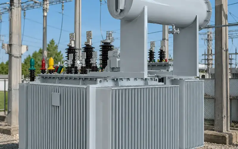
Load tap changers: on-load (OLTC) vs off-circuit tap changers
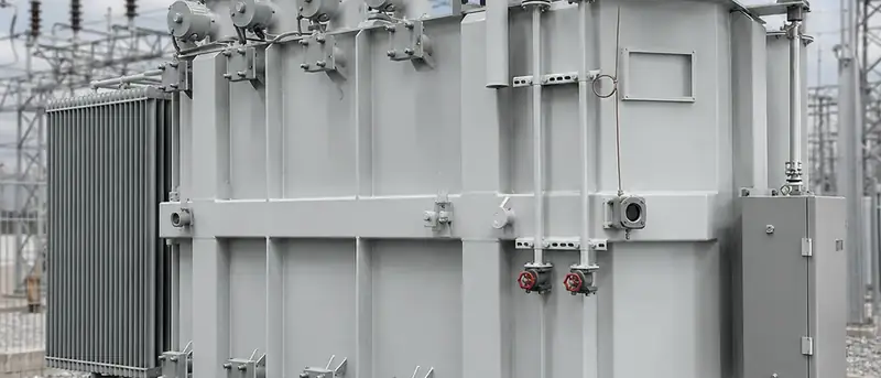
A load tap changer (on-load tap changer, OLTC) adjusts a transformer's turns ratio while it carries load, so the output voltage can be regulated continuously as the network voltage and load change. An off-circuit tap changer (also called a no-load or de-energised tap changer) changes the ratio only when the transformer is switched off, and is used to set the voltage once for a site. Distribution transformers usually have the off-circuit type; grid and large industrial transformers usually have an OLTC.
Key takeaways
- Both types change the number of active turns, usually on the HV winding, to shift the voltage ratio.
- Off-circuit tap changers are simple and cheap. A typical IEC range is ±2 × 2.5 percent (five positions), set at commissioning.
- An OLTC regulates under load, controlled by an automatic voltage regulator (AVR) relay. Typical ranges are around ±10 percent in 1 to 1.7 percent steps.
- An OLTC adds cost, size, maintenance and a failure mode, so specify one only where the voltage really varies in service.
- IEC 60214-1 covers tap-changer performance and testing; IEEE C57.131 is the North American equivalent.
What are transformer taps and why are they needed?
Transformer taps are connection points brought out from a winding at different numbers of turns. Because the voltage ratio equals the turns ratio, selecting a tap with more or fewer turns changes the output voltage for the same input.
Taps are almost always placed on the HV winding, for three reasons: the HV winding has more turns so each step is a finer percentage, the HV current is lower so the contacts are smaller, and in a typical step-down design the HV winding sits outside the LV winding where connections are easier to reach.
Voltage regulation is needed because the supply voltage at a substation varies with network loading and distance from the source, and because the transformer itself drops voltage under load through its impedance. A 6 percent impedance transformer at full load and 0.8 power factor can lose several percent of output voltage between no load and full load. Taps let the user compensate.
On the rating plate, the tap positions are listed with their voltages. Under IEC 60076-1, the principal tap is the one to which rated quantities refer, and the tapping range is stated as, for example, 11 kV ±2 × 2.5 %.
How does an off-circuit (no-load) tap changer work?
The off-circuit tap changer is a rotary or linear selector switch mounted inside the tank, operated by a handle on the cover or tank wall. Each position connects a different section of the HV winding. Because the switch is not designed to make or break current, the transformer must be de-energised and isolated on both sides before the handle is moved. IEC 60214-1 calls it a de-energised tap-changer (DETC).
A typical procedure:
- Isolate and earth the transformer on HV and LV sides.
- Release the handle lock, move to the new position and confirm the indicator.
- Rotate through all positions a few times if the unit has been on one tap for years, to wipe oxide film from the contacts, then return to the chosen tap.
- Check winding resistance or ratio on the new tap if practical.
- Re-lock the handle and re-energise.
The common IEC distribution arrangement is ±2 × 2.5 percent: positions at +5, +2.5, 0, −2.5 and −5 percent. North American distribution units commonly use two taps above and two below rated voltage at 2.5 percent steps as well. Our 20 kV to 400 V transformer with a no-load tap changer is a typical example.
How does an on-load tap changer (OLTC) work?
An OLTC must move from one tap to the next without ever opening the load circuit and without short-circuiting the turns between taps. It does this in two parts:
- Tap selector: selects the next tap while carrying no switching current.
- Diverter switch (or selector switch in combined designs): transfers the load from the old tap to the new one, using a transition impedance to limit the circulating current while both taps are briefly bridged.
There are two main transition principles:
- Resistor type: two transition resistors are inserted for a few tens of milliseconds during the changeover. This is the usual design in IEC markets.
- Reactor type: a preventive autotransformer (reactor) bridges the taps, and the bridging position can itself be used as a running position, doubling the number of steps. This is common in North American practice.
Switching arcs occur in the diverter. Older designs break current in oil inside a separate compartment, so the oil carbonises and needs periodic replacement. Modern designs often use vacuum interrupters, which keep arcing out of the oil and extend maintenance intervals considerably.
The OLTC is either mounted inside the main tank with its diverter in a separate oil-tight compartment, or housed in an external compartment bolted to the tank. Either way it has its own conservator section or oil volume, a protective relay (oil-flow or pressure type), and a motor drive mechanism.
What is a typical OLTC tap range?
| Feature | Off-circuit (DETC) | On-load (OLTC) |
|---|---|---|
| Operates while energised | No | Yes |
| Typical range | ±2 × 2.5 % (±5 %) | Around ±10 %, e.g. ±8 × 1.25 % or 32 steps of 0.625 % |
| Number of positions | 3 to 7 | 9 to 35 |
| Control | Manual handle | Motor drive with AVR relay, local or remote |
| Typical application | Distribution transformers, most dry-type units | Grid, sub-transmission and large industrial transformers; furnace and rectifier units |
| Relative cost | Low | High; can be a significant share of a medium-size power transformer |
| Maintenance | Exercise contacts during shutdowns | Inspection by number of operations or time; oil or vacuum interrupter checks |
| Main standard | IEC 60214-1, IEC 60076-1 | IEC 60214-1, IEEE C57.131 |
A range such as ±8 × 1.25 percent gives 17 positions. The North American pattern of ±10 percent in 32 steps of 5/8 percent gives 33 positions, using the reactor bridging positions. The ranges above are typical figures only; the actual range is chosen from network studies.
How is an OLTC transformer controlled?
The OLTC motor drive receives raise and lower commands from an automatic voltage regulator relay, which compares the measured secondary voltage with a set point. Key settings are:
- Set point: the target voltage, often slightly above nominal to allow for feeder drop.
- Bandwidth (dead band): how far the voltage can deviate before a tap change is called. It must be wider than one tap step, otherwise the OLTC hunts between positions.
- Time delay: typically tens of seconds before the first operation, so short dips do not cause unnecessary operations.
- Line drop compensation: raises the set point with load current to hold voltage at a point further down the feeder.
- Parallel control: when two OLTC transformers run in parallel, master-follower or circulating-current minimisation keeps them on matched taps.
The drive also carries interlocks: end-position limits, step-by-step operation, an operation counter, and blocking on overcurrent or undervoltage. Position is reported to SCADA through a position transmitter.
For utility substations at 66 kV and above, an OLTC power transformer at 110/115 kV is normal. For a solar or wind collector substation, OLTCs are increasingly specified to meet reactive power and voltage requirements of grid codes; see the solar plant grid-tie transformer for a typical configuration.
When should you specify an on-load tap changer?
Specify an OLTC when:
- the HV supply voltage varies by more than the load can tolerate, for example at the end of a long overhead line;
- the load changes widely through the day and voltage at the LV bus must be held within a narrow band;
- grid code compliance requires voltage or reactive power control at the point of connection;
- the transformer is a step-up unit for generation that must follow a dispatch voltage set point;
- the process needs voltage variation, as with arc furnaces or electrolysis rectifiers.
Stay with an off-circuit tap changer when the supply is stiff and stable, the transformer is a distribution unit below a few MVA, and the voltage only needs setting once. For most 11 kV, 22 kV and 33 kV distribution transformers in the range covered by our oil-immersed transformer category, that is the case. Some utilities now use on-load regulating distribution transformers for networks with high rooftop PV penetration, but these remain a specialist choice.
If you are unsure, include the HV voltage range and load profile in your enquiry. Our transformer RFQ checklist lists the data to include.
What maintenance does a tap changer need?
Off-circuit tap changers need very little: exercise them through all positions during planned outages and check winding resistance on each tap during commissioning tests. A high or unbalanced resistance on one tap points to a poor contact. The routine factory checks are described in transformer routine tests before shipment.
OLTCs need a maintenance plan based on the manufacturer's instructions, usually triggered by number of operations or years in service, whichever comes first. Typical activities:
- Read the operation counter and compare it with the inspection interval.
- Test the diverter oil (breakdown voltage, moisture) for oil-switching designs, or check vacuum interrupter wear indicators.
- Inspect contacts and transition resistors for wear.
- Check the motor drive, limit switches, heater and the protective relay.
- Run dynamic resistance measurement to confirm clean transitions.
Dissolved gas analysis of the main tank is useful too, but if the OLTC compartment leaks into the main tank the arcing gases can mislead the interpretation. See our transformer oil guide for DGA basics.
Frequently asked questions
Can I change taps on a no-load tap changer while the transformer is energised?
No. An off-circuit or de-energised tap changer is not designed to make or break current. Operating it live can draw an arc, damage the contacts and cause an internal fault. Isolate the transformer on both sides first.
Which winding has the tap changer?
Usually the HV winding, because its lower current means smaller contacts and its higher number of turns allows finer steps. LV tapping is used only in special designs.
What does ±2 × 2.5 % mean on a nameplate?
It means two tap steps above and two below the principal tap, each step changing the HV voltage by 2.5 percent, for a total range of ±5 percent. On an 11 kV unit, the tap voltages are 11.55, 11.275, 11, 10.725 and 10.45 kV.
Is a dry-type transformer available with an OLTC?
It is possible but uncommon. Most cast-resin dry-type transformers use off-circuit tapping links on the HV coils. On-load regulation in dry-type designs is a special application and should be discussed early.
What is the difference between a load tap changer and a voltage regulator?
A load tap changer is part of a power transformer. A step voltage regulator is a separate autotransformer with its own tap changer, placed on a feeder to boost or buck voltage. Both use similar on-load switching principles.
Discuss your voltage regulation needs
Send us your single-line diagram, HV voltage range and load profile, and our engineers will recommend an off-circuit or on-load tap changer, tap range and control scheme in a technical proposal. Contact Toppower Asia. The tap-changer performance requirements referenced here are in IEC 60214-1:2014.