Transformer vector groups explained: Dyn11, Yyn0, Dyn1, YNd11

A transformer vector group describes how the HV and LV windings are connected (delta, star or zigzag), whether a neutral is brought out, and the phase shift between HV and LV voltages, expressed as a clock number in steps of 30°. Dyn11, for example, means delta HV, star LV with neutral, and LV leading HV by 30°. It is the most common choice for distribution.
Key takeaways
- Capital letters describe the HV winding, lower-case letters the LV winding; N or n means the neutral is brought out to a terminal.
- The clock number is the LV phase lag behind HV in multiples of 30°. Dyn11 has the LV leading by 30°, Dyn1 has it lagging by 30°.
- Dyn11 suits four-wire LV networks: the delta HV winding handles unbalanced loads and traps triplen harmonics, and the LV neutral can be fully loaded and earthed.
- Yyn0 is simpler but has limited neutral loading capability on three-limb cores, so it suits mainly balanced loads.
- Transformers in parallel must have compatible vector groups, matching ratios and similar impedances. Getting the vector group wrong is one of the costliest specification mistakes.
How do you read a vector group code?
The code has three parts, defined in IEC 60076-1:
- HV winding connection (capital letter): D for delta, Y for star (wye), Z for zigzag. YN means star with the neutral brought out.
- LV winding connection (lower-case letter): d, y or z, with n if the LV neutral is brought out.
- Clock number (0 to 11): the phase displacement between HV and LV line voltages.
So Dyn11 reads as: HV delta, LV star with neutral brought out, clock 11. YNd11 reads as: HV star with neutral brought out, LV delta, clock 11.
Terminal markings follow the same logic. IEC practice labels HV terminals 1U, 1V, 1W and LV terminals 2U, 2V, 2W, with 2N for the LV neutral.
What does the clock number mean?
Imagine a clock face. The HV line-to-neutral voltage phasor (real or virtual) points to 12 o'clock. The corresponding LV phasor points to the hour given by the clock number. Each hour is 30°, and the displacement is measured as the LV lagging the HV in the clockwise direction.
| Vector group | HV | LV | LV phase relative to HV | Typical use |
|---|---|---|---|---|
| Dyn11 | Delta | Star, neutral out | Leads by 30° | Distribution, IEC markets |
| Dyn1 | Delta | Star, neutral out | Lags by 30° | Distribution where networks use clock 1; matches the ANSI delta-wye convention |
| Dyn5 | Delta | Star, neutral out | Lags by 150° | Some utility specifications |
| Yyn0 | Star | Star, neutral out | In phase | Mainly balanced loads; some legacy networks |
| YNd11 | Star, neutral out | Delta | Leads by 30° | Step-up and subtransmission step-down where HV side needs an earthed star point |
| Yzn11 | Star | Zigzag, neutral out | Leads by 30° | Small units with heavily unbalanced loads |
Dyn11 and Dyn1 look identical on paper apart from the clock number. The difference is which LV phase is connected across which HV delta winding. They cannot be paralleled directly with each other without changing phase connections.
North American practice under IEEE C57.12.00 requires the low voltage to lag the high voltage by 30° for delta-wye and wye-delta three-phase transformers, which in IEC notation is clock 1. A US-pattern pad-mounted transformer is therefore not automatically interchangeable with an IEC Dyn11 unit. Our article on IEC 60076 vs IEEE C57 transformer standards covers other differences between the two systems.
Why is Dyn11 the standard choice for distribution transformers?
Distribution transformers feed four-wire LV networks (three phases plus neutral) serving single-phase and three-phase loads. Single-phase loads are never perfectly balanced. Dyn11 handles this well for several reasons:
- Unbalanced loads. A single-phase load on the star LV winding draws current through one delta winding on the HV side. The current appears in two HV lines, and the ampere-turns balance on each limb. There is no zero-sequence flux forced into the core, so the LV neutral can carry substantial current without overheating the tank or distorting the voltages.
- Triplen harmonics. Third, ninth and other triplen harmonic currents from single-phase non-linear loads are zero-sequence. They circulate in the delta winding instead of flowing into the MV network. The transformer still has to be designed for the extra heating, which we cover in how to size a distribution transformer.
- Stable neutral and earthing. The LV star point can be solidly earthed for TN or TT systems, giving a stable neutral voltage and enough earth fault current to operate protective devices.
- Independence of MV earthing. The delta HV winding has no neutral, so the MV network's earthing method (solid, resistance, resonant or isolated) is not affected by the transformer, and LV earth faults do not drive zero-sequence current into the MV system.
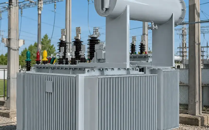
For these reasons most IEC-based utilities and industrial specifications default to Dyn11 for transformers feeding 400 V or 415 V networks. Typical examples are our oil-filled distribution transformers for 11 to 33 kV systems, which are offered in Dyn11 as well as other groups.
When is Yyn0 used, and what are its limits?
Yyn0 has star windings on both sides and no phase shift. It is simple to build and lets you parallel with existing Yyn0 units in networks that adopted it historically.
The main limitation is neutral loading. In a Yyn0 transformer, an LV single-phase load has no balancing current path on the HV side because the HV star point is not connected to a source neutral. The unbalanced ampere-turns create zero-sequence flux. In a three-limb core-type design, that flux has no low-reluctance return path and closes through the air, the tank and structural steel. The results are:
- heating of the tank and clamping structure,
- neutral point displacement, so phase voltages become unequal under unbalanced load,
- low LV earth fault current, which can make fault clearance slow.
For this reason, utilities and design codes that still accept Yyn0 usually limit the permissible neutral current to a fraction of rated current. Five-limb cores, shell-type cores or a tertiary delta winding improve behaviour but add cost. Yyn0 is acceptable where loads are mostly three-phase and balanced, such as motor-dominated industrial supplies. For mixed commercial and residential loads, Dyn11 is the safer choice.
What about Dyn1, Dyn5 and YNd11?
Dyn1 has the same winding arrangement and behaviour as Dyn11, with a -30° rather than +30° shift. It is used where the existing network was built around clock 1, and it corresponds to the ANSI delta-wye convention.
Dyn5 appears in some utility specifications. Our Ethiopia EEU-spec box substation is an example of a product configured with a Dyn5 transformer to match a utility standard. The lesson is to always follow the network owner's vector group, not a generic default.
YNd11 puts the earthed star on the HV side and the delta on the LV side. It is typical of generator step-up transformers and of some subtransmission substations where the HV network requires a solidly earthed neutral and the LV side is a three-wire system. Because the delta LV side provides no neutral, the LV network is earthed separately, for example through an earthing transformer, if required.
In renewable plants, step-up transformers between inverters and the MV collector system are often specified with a delta or star configuration determined by the inverter manufacturer's earthing requirements. Confirm the vector group with the inverter supplier before ordering.
What are the conditions for parallel operation?
When two or more transformers share a busbar on both the HV and LV sides, they must meet these conditions, consistent with the guidance in IEC 60076-8:
- Same phase displacement (clock number). Two transformers with different clock numbers produce LV voltages at different angles, and large circulating currents flow as soon as both are connected. Dyn11 with Dyn11 is fine; Dyn11 with Yyn0 is not.
- Same voltage ratio, within tolerance, and similar tapping ranges. Ratio differences drive circulating current even with no load. Tap positions must be coordinated.
- Similar short-circuit impedance. Load sharing is inversely proportional to impedance. A unit with lower impedance takes more than its share of the load and can overload while the other is lightly loaded. Practice is to keep impedances within a tight tolerance of each other and to check impedance variation across the tap range.
- Similar ratings. Avoid combining units with widely different ratings. A ratio beyond about 1:2 is generally discouraged, partly because optimal impedances differ with size.
- Same phase sequence, verified at commissioning.
Transformers with clock 1 and clock 11 can sometimes be paralleled by reconnecting two phases on both the HV and LV sides of one unit. This changes the phase labelling and must be engineered, documented and tested; it is not a field improvisation.
How should you specify the vector group?
Include the following in your enquiry or technical specification:
- Vector group (for example Dyn11) and whether any other group is acceptable.
- Neutral: whether the LV neutral is brought out, the neutral terminal current rating, and the earthing system (TN-S, TN-C-S, TT or IT).
- Parallel operation: if the new unit will run in parallel with existing ones, provide the nameplate data of those units, including vector group, ratio, tapping range and measured impedance.
- Terminal markings and phase sequence required by the network owner.
- Applicable standard (IEC 60076-1 or IEEE C57.12.00) so the clock convention is unambiguous.
The vector group is confirmed at the factory as part of routine testing: IEC 60076-1 includes measurement of voltage ratio and check of phase displacement among the routine tests on every unit. See transformer routine tests before shipment for the full list, and our transformer RFQ checklist for everything else to include.
Frequently asked questions
What is the difference between Dyn11 and Dyn1?
Both are delta HV and star LV with neutral. In Dyn11 the LV voltage leads the HV voltage by 30°, while in Dyn1 it lags by 30°. They behave the same electrically but cannot be paralleled with each other without changing phase connections.
Why is Dyn11 preferred over Yyn0?
Dyn11 can carry unbalanced single-phase loads and full neutral current without zero-sequence flux problems, traps triplen harmonics in the delta winding and isolates LV earth faults from the MV earthing system. Yyn0 has limited neutral loading on three-limb cores and is best restricted to balanced loads.
Can a Dyn11 transformer be paralleled with a Yyn0 transformer?
No. Their LV voltages are 30° apart, which causes large circulating currents. Parallel units need the same clock number, matching ratios and similar impedances.
What vector group is used in North America?
IEEE C57.12.00 requires the LV to lag the HV by 30° for delta-wye and wye-delta three-phase transformers, which is clock 1 in IEC notation. Specify carefully when a project mixes IEC and ANSI equipment.
Does the vector group affect earthing?
Yes. A star winding with neutral brought out (yn or YN) provides an earthing point; a delta winding does not. In Dyn11 the LV neutral is earthed to form a TN or TT system, while the MV network keeps its own earthing method.
How is the vector group verified?
The check of phase displacement is a routine test under IEC 60076-1, performed on every transformer before shipment. It is also good practice to check phase sequence and phasing on site before energising and before closing any parallel connection.
Send us your network details
If you need to confirm the right vector group or match a new transformer to existing units, send us your single-line diagram, earthing system and nameplate data of any transformers that will run in parallel. We will check compatibility and return a technical proposal. Contact our engineering team. The definitions used here come from IEC 60076-1, with parallel operation guidance in IEC 60076-8.