What is a substation? Types, equipment and layout
What is a substation? It is a node in the power network where voltage is changed by transformers, circuits are switched and protected, and power is measured and routed between lines and feeders. Transmission substations connect high-voltage lines and step voltage down to sub-transmission levels; distribution substations feed medium-voltage networks; and small transformer substations supply low voltage to buildings, plants and inverters.
Key takeaways
- Every substation combines three jobs: voltage transformation (in most cases), switching and protection, and measurement and control.
- Main types are transmission, sub-transmission, distribution, switching, collector (for solar, wind and storage), customer or industrial, and converter substations.
- Core electrical substation equipment includes power transformers, circuit breakers, disconnectors, earthing switches, instrument transformers, surge arresters, busbars, protection relays and an earthing grid.
- The busbar scheme (single, double, breaker-and-a-half, ring) sets how reliable and maintainable the substation layout is.
- Small MV/LV substations are increasingly delivered as factory-built prefabricated units.
What is a substation and what does it do?
The answer to "what is a substation" is easiest to see from its functions:
- Transforming voltage. Generators produce power at medium voltage; transformers step it up for efficient transmission and step it down again near the load. Most substations contain at least one power transformer.
- Switching. Circuit breakers and disconnectors connect and isolate lines, transformers and feeders for operation and maintenance.
- Protecting. Relays detect faults from current and voltage transformer signals and trip the breakers that isolate the faulted section, so the rest of the network stays in service.
- Measuring and controlling. Metering, power quality monitoring and a substation automation or SCADA system let operators see and control the network remotely.
- Compensating. Capacitor banks, reactors or static compensators may be installed to control voltage and reactive power.
Some substations have no transformer at all: a switching substation simply connects several lines at the same voltage.
What are the main types of power substation?
| Type | Typical voltages | Main purpose |
|---|---|---|
| Generator step-up / power plant substation | Generator voltage to transmission voltage | Raises generator output for transmission |
| Transmission substation | 220 kV and above, connected to lower transmission levels | Interconnects high-voltage lines and transforms between transmission levels |
| Sub-transmission or grid substation | For example 132/33 kV, 110/20 kV, 66/11 kV | Feeds regional networks and large industrial customers |
| Distribution (primary) substation | For example 33/11 kV, 35/10 kV, 69/13.8 kV | Supplies medium-voltage feeders in towns and districts |
| Secondary or transformer substation | For example 11/0.4 kV, 22/0.4 kV, 13.8/0.48 kV | Supplies low voltage to buildings, streets and plants |
| Collector substation | Inverter or turbine MV collection to grid voltage | Gathers output from solar, wind or battery storage plants |
| Switching substation | One voltage level | Connects and sectionalises lines without transformation |
| Converter substation | AC to DC and back | Terminates HVDC links or connects asynchronous systems |
| Mobile substation | Usually MV or sub-transmission | Temporary or emergency supply on a trailer or skid |
Voltage examples vary by country. IEC and ANSI also draw the boundaries between voltage classes differently, as explained in our article on voltage levels: LV, MV and HV.
What equipment is inside an electric substation?
The electrical substation equipment list is similar from 11 kV to 400 kV; only size and technology change.
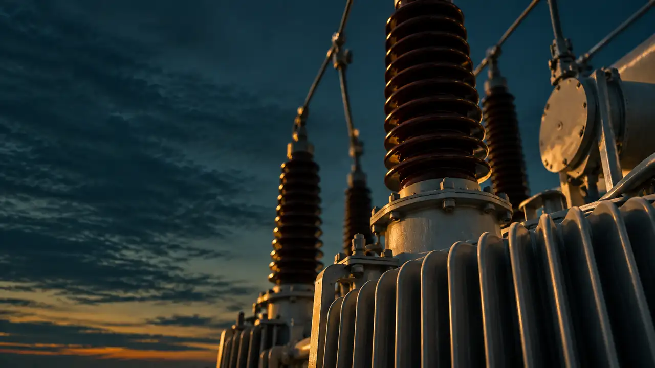
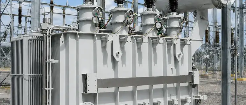
- Power transformers. The largest and most expensive item, usually oil-immersed with ONAN or ONAF cooling, often with an on-load tap changer to regulate voltage. Smaller substations may use cast-resin dry-type units indoors.
- Circuit breakers. Interrupt load and fault currents. At medium voltage these are almost always vacuum breakers; at transmission voltages SF6 has long been standard. See vacuum vs SF6 circuit breakers.
- Disconnectors (isolators) and earthing switches. Provide visible or verified isolation and earthing for safe maintenance. They are not designed to interrupt load current.
- Current and voltage transformers. Scale the primary quantities down for protection relays and meters.
- Surge arresters. Limit lightning and switching overvoltages, typically at line entries and transformer terminals.
- Busbars. Rigid tubes, strung conductors or enclosed bars that connect the bays.
- Protection, control and communication. Numerical relays, bay controllers, RTUs or substation automation, often using IEC 61850 communication.
- Auxiliary systems. A station service transformer, AC and DC distribution, battery and charger to keep protection working during outages.
- Earthing grid and lightning protection. A buried mesh limits step and touch voltages during earth faults; shield wires or masts protect outdoor yards.
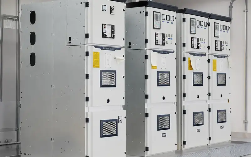
- Medium-voltage switchgear. On the secondary side, a lineup of indoor panels distributes power to outgoing feeders, typically metal-clad withdrawable panels or gas-insulated cabinets.
How is the substation transformer selected?
The substation transformer sets the capacity of the whole installation. Key specification points:
- Rated power based on the present load, expected growth and the N-1 criterion. Many primary substations have two transformers, each able to carry most or all of the load if the other is out.
- Voltage ratio and tapping range, plus whether an on-load tap changer is needed to hold the secondary voltage as load and source voltage change.
- Vector group and neutral earthing, for example YNd11 or Dyn11, depending on how the networks on both sides are earthed and how they must be phase-shifted relative to each other.
- Impedance, which limits fault current on the secondary side and affects voltage regulation and parallel operation.
- Cooling class, losses and noise, which affect running cost and the space needed.
Our power transformer range covers sub-transmission units such as the three-phase 110 kV substation transformer.
What is a typical substation layout?
The substation layout is mainly defined by the busbar scheme, which balances cost against reliability and the ability to maintain equipment without outages.
| Busbar scheme | How it works | Strengths | Limitations |
|---|---|---|---|
| Single busbar | All circuits connect to one bus | Simple, cheapest, compact | A bus fault or bus maintenance takes the whole substation out |
| Sectionalised single busbar | Bus split by a bus-section breaker | A bus fault affects only one section | Each circuit still depends on its own bus section |
| Double busbar | Each circuit can be switched to either of two buses | Flexible operation and maintenance | More equipment and more complex interlocking |
| Main and transfer bus | A transfer bus allows a breaker to be bypassed | Breaker maintenance without losing the circuit | Extra bus and switching steps |
| Ring bus | Breakers arranged in a closed loop | Good reliability for few circuits | Becomes complex as circuits are added |
| Breaker-and-a-half | Three breakers serve two circuits between two buses | Very high reliability, common at transmission level | Highest cost and space |
Beyond the busbar scheme, the layout also follows from the insulation technology. An air insulated substation spreads equipment over an outdoor yard with clearances set by the voltage; a gas insulated substation compresses the same functions into metal-enclosed modules in a building. Our comparison of gas-insulated vs air-insulated switchgear covers that decision.
A real layout also allows for transformer firewalls or separation distances, oil containment, cable trenches, access roads, a control building and future bays. Installations above 1 kV AC are generally designed to IEC 61936-1 in IEC markets, with earthing design commonly checked against IEEE 80.
How are small MV/LV substations built today?
At distribution level, many transformer substations are no longer built brick by brick. A prefabricated or box-type substation combines MV switchgear, a distribution transformer and an LV switchboard in a factory-tested enclosure, type-tested to IEC 62271-202. It shortens site work and makes performance more predictable. See prefabricated and mobile substations and our transformer substation range.
Our representative configuration for a Kenya 33 kV/11 kV urban distribution substation shows a typical primary substation arrangement.
Frequently asked questions
What is the difference between a substation and a transformer?
A transformer is one piece of equipment that changes voltage. A substation is the whole installation around it: switchgear, protection, measurement, busbars, earthing and auxiliary systems. A small pole-mounted transformer on its own is not normally called a substation.
Are electric substations dangerous to live near?
Substations are designed with fencing, earthing and clearances so that the public is protected from electric shock. Magnetic fields fall off quickly with distance from the equipment. Noise from transformers can be noticeable close by and is limited through design and siting.
How much land does a power substation need?
It depends on the voltage, number of bays, busbar scheme and insulation technology. A small MV/LV prefabricated substation may occupy only a few square metres, while an outdoor high-voltage air insulated substation needs a large yard. Gas insulated substations reduce the area substantially.
What is a collector substation?
A collector substation gathers power from many inverters or wind turbines through MV collection cables and steps it up to the grid voltage. It typically includes MV switchgear for each collection circuit, one or more main power transformers, HV switchgear and the metering and protection required by the grid code.
What standards apply to substations?
In IEC markets, IEC 61936-1 covers power installations above 1 kV AC, with the IEC 62271 series for switchgear and IEC 60076 for transformers. Prefabricated MV/LV substations follow IEC 62271-202. In ANSI markets, IEEE standards and the local electrical code apply, and many utilities add their own specifications.
Plan your substation equipment
Send us your single-line diagram, voltage levels, load forecast and site conditions. Our engineers will propose the transformers, switchgear and substation configuration in a technical proposal. Contact our engineering team.