
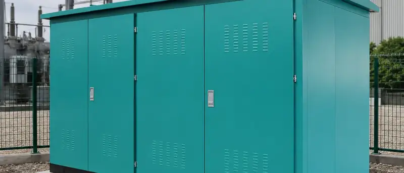
Application example · Kenya · 50 Hz
33 kV/11 kV Urban Distribution Substation
Expanding cities put a 33 kV/11 kV substation under two competing pressures.
- Country
- Kenya
- System
- 33 kV/11 kV
- Frequency
- 50 Hz
- Package
- 9 equipment items
Project snapshot
| Country | Kenya |
|---|---|
| Typical setting | Nairobi and similar fast-growing urban / peri-urban areas (illustrative) |
| Application | Reinforcement of urban and peri-urban distribution capacity |
| System | 33 kV/11 kV distribution substation — power transformer, ring main unit, LV switchgear, power distribution cabinets and associated accessories |
| Voltage | 33 kV supply side / 11 kV distribution side |
| Frequency | 50 Hz |
| Design standards | IEC 60076 series (transformer), IEC 62271-200 (MV switchgear), IEC 61439-1/-2 (LV assemblies), IEC 60529 (degree of enclosure protection) |
Site and grid challenges
Expanding cities put a 33 kV/11 kV substation under two competing pressures. Demand keeps climbing, so the station must add capacity without introducing new outage risk — yet the plots available inside an established urban area are small, irregular and rarely chosen with electrical clearances in mind.
On the supply side, 33 kV in this kind of network usually arrives as a ring or a looped radial circuit. A ring main unit is the logical switching choice: it can accept supply from either direction and isolate a faulted cable section while the transformer stays in service. Outdoor air-insulated busbars at 33 kV would need far more clearance than a city plot can offer, so compact, metal-enclosed and compartmented switching is the practical answer.
The 11 kV and LV side raises a different issue — fault energy and discrimination. As distribution capacity grows, the prospective short-circuit current at the LV board rises with it. The board's short-time withstand rating therefore has to be selected from the transformer impedance and upstream fault level, rather than from the connected load alone.
Climate adds a further layer. Nairobi-type highland sites combine sustained humidity, seasonal dust and frequent lightning on overhead feeders. Insulation coordination, surge arrester selection and enclosure sealing are therefore practical reliability measures, not paperwork items.
Typical equipment package
What a project of this type usually includes, and the engineering points that decide each item.
| Equipment | Role | Engineering notes |
|---|---|---|
| Power transformer | Steps the 33 kV supply down to 11 kV | Capacity, vector group and impedance derived from the load forecast and fault-level study for the specific network |
| 33 kV ring main unit | Switching and protection for the incoming ring circuit | Metal-enclosed design to IEC 62271-200; internal arc class and cable compartment layout selected to suit the incoming cables |
| 11 kV / LV switchgear | Main outgoing distribution board | IEC 61439-1/-2 assembly; short-time withstand coordinated with transformer impedance and cable let-through energy |
| Power distribution cabinets | Feeder and auxiliary supply enclosures | Form of separation, busbar current density and termination space set by the outgoing circuit schedule |
| Protection and metering | Overcurrent, earth-fault and transformer protection with CTs and VTs | Discrimination arranged across incoming, transformer and outgoing stages; settings agreed with the network operator |
| Earthing system | Station earth grid, equipment bonding and neutral earthing | Conductor size based on fault current and clearing time; step and touch voltages assessed in line with IEC 61936-1 practice |
| Surge protection | Arresters on exposed incoming and outgoing circuits | Arrester rated voltage chosen for the system earthing method and expected temporary overvoltages |
| Cables and accessories | MV and LV cables, terminations, glands and supports | Bending radius, screen bonding and gland sealing follow the accessory supplier's approved procedure |
| Civil and enclosure interface | Foundations, cable trenches, ventilation and access | Trench geometry and pulling points planned so no cable is bent below its minimum radius |
Stage by stage
Site layout planning
The general arrangement drawing is where a substation of this type is really decided. It fixes the 33 kV entry point, the transformer position and the relationship between the MV switching room and the LV distribution equipment. Those decisions set cable lengths, which in turn govern voltage drop, the screen-bonding method and the maximum safe pulling tension. The layout must also leave a clear withdrawal route for the transformer, because a unit that cannot be removed later turns every future repair into a major job. Wall clearances, ventilation paths and the earth grid footprint are all settled at this stage, before any foundation is cast.
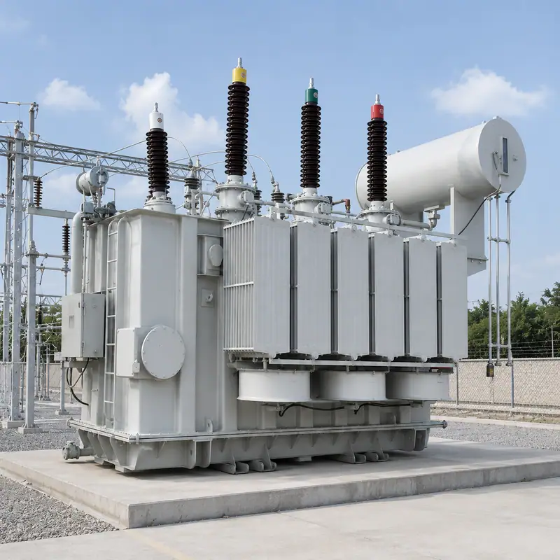
Illustrative product image: 66kV to 415V Step-Down Transformer 2500 kVA, Three-Phase ONAN Oil-Immersed Unit · View product Stage 1 of 5Transformer placement
Setting the transformer is normally the heaviest and most critical lift in a station like this. Slings attach only to the manufacturer's lifting lugs, and the rigging is arranged so the load acts through the true centre of gravity — which lies toward the core and windings rather than the middle of the tank. The plinth is checked for level before the unit is lowered, since uneven support stresses the tank base and disturbs gasket compression at the cover and radiator flanges. After placement, the oil level, gas relay and gasketed joints are inspected, and the unit is allowed to settle before any connections are made.

Illustrative product image: Compact Ring Main Unit for 6.3kV, 10kV and 12kV Networks, 4000A Indoor Cabinet · View product Stage 2 of 5MV switching
Once the 33 kV ring main unit is set, levelled and anchored, the incoming and interconnecting cables are terminated. This is the step where most MV workmanship faults originate: the semiconducting screen cut-back length, cleanliness of the insulation surface and correct seating of the stress control element decide the life of the termination. Cable screens are bonded to the RMU earth bar with a conductor rated for the earth-fault duty. Interlocks between the load-break switch, the earthing switch and the cable compartment door are physically operated and confirmed before the compartment is closed.

Illustrative product image: GCS Draw-Out LV Distribution Switchboard 1kV 1600A, IP65 Galvanized Enclosure · View product Stage 3 of 5LV distribution
LV switchboard sections are aligned and bolted so the busbar joints meet without force; a joint pulled into position carries residual stress for its whole service life. Every busbar and terminal bolt is tightened to the specified torque and marked. Too little torque raises contact resistance and creates a future hot spot, while too much yields the bolt and lets the joint relax over time. Insulation resistance is measured between phases and to earth, and protection settings are compared with the discrimination study before the board is made live.

Illustrative product image: 800V 630A Withdrawable Low Voltage Distribution Panel with Al-Zn Coated Enclosure · View product Stage 4 of 5Feeder distribution
Distribution cabinets are positioned, bonded and cabled. The protective earth path of each cabinet is proved by a continuity test back to the main earth bar, because powder-coated panels cannot be relied on as conductors — bonding is made through dedicated earth studs with serrated washers. Gland plates seal each cable entry to maintain the declared IP rating, and non-magnetic gland plates are used where single-core cables pass through, preventing induced circulating currents and local heating. Circuit labels and as-built schedules are completed at this point rather than after energisation.
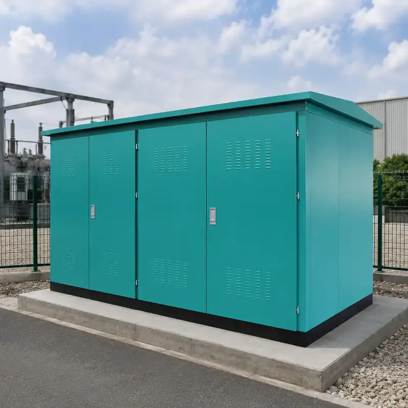
Illustrative product image: 33 kV 630 kVA Outdoor Box-Type Distribution Substation, Three-Phase 50/60 Hz · View product Stage 5 of 5Complete configuration
Before a substation of this type is switched on, it is verified as a single integrated system. Transformer ratio and vector group are checked, insulation resistance and, where specified, oil condition are recorded, earth grid resistance is measured, and protection is tested end to end by injection so that relay, CT circuit and trip coil are proven together. Interlocks, labels, warning signs and access control are confirmed. Energisation then follows a controlled sequence, with load introduced in steps while temperatures and readings are monitored.
What Toppower can configure
For an enquiry of this kind, Toppower Asia can configure the transformer voltage ratio and tapping range, rated capacity, vector group and impedance, with copper or aluminium windings. Oil-immersed units (ONAN or ONAF cooling) and cast-resin dry-type units (AN or AF cooling) are both available, with insulation class, temperature-rise limits and overload capability set for the site's ambient conditions. Enclosures can be specified to the required IP rating and corrosion protection class, with anti-condensation heaters and ventilation for humid locations. Protection and monitoring options range from conventional relays through winding-temperature indication, gas relay and oil-level alarms to digital monitoring over IEC 61850, Modbus RTU/TCP or DNP3. RMU and LV assemblies can be extended, rearranged or supplied with a different internal arc classification to suit the switchroom.
Information needed for a quotation
Tick what you can already provide; checked items are added to your enquiry.