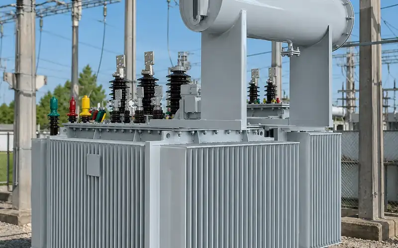
Pad-mounted transformers: types, sizes and how they work

A pad mounted transformer is a liquid-filled distribution transformer sealed in a locked, tamper-resistant steel cabinet that sits on a concrete pad and is fed by underground cable. It steps a medium-voltage primary, typically 12.47 kV to 34.5 kV, down to a service voltage such as 120/240 V or 480Y/277 V. Units come in single-phase and three-phase versions, radial or loop feed, and dead-front or live-front.
Key takeaways
- A padmount transformer combines the core and coil, under-oil switching and fusing, and the cable terminations in one enclosure, so no fence or separate switchgear is needed.
- Single-phase units (IEEE C57.12.38, 250 kVA and smaller) serve residential underground loops; three-phase units (IEEE C57.12.34, up to 10 MVA) serve commercial, industrial and renewable sites.
- Loop feed lets the primary cable pass through to the next transformer and allows sectionalising; radial feed terminates the cable.
- Dead-front construction, with separable insulated connectors, is the norm for new installations in public areas.
- Footprint is driven by kVA, losses and cooling, voltage class, feed arrangement and the cable compartment depth set by the standard.
How does a pad mounted transformer work?
Electrically, a pad-mounted transformer is an ordinary two-winding distribution transformer; the packaging is what differs. The core and windings sit in a sealed tank filled with mineral oil or a less-flammable natural ester fluid, cooled naturally through tank walls, corrugated panels or radiators. At the front, a compartment divided by a steel barrier holds the high-voltage terminations on the left and the low-voltage terminations on the right. The doors are interlocked so the HV door can only be opened after the LV door, and both are secured with a recessed penta-head bolt and padlock.
Cables rise through an opening in the concrete pad directly into the compartment, so nothing energised is exposed above ground.
Inside the tank, most designs also carry:
- An oil-immersed loadbreak switch to energise or isolate the transformer and, on loop-feed units, to sectionalise the cable.
- A bayonet fuse, a hot-stick removable expulsion fuse holder that clears secondary faults and overloads.
- A partial-range current-limiting fuse under oil, in series with the bayonet fuse, which clears high-current internal faults.
- Gauges and fittings: liquid level, top-oil temperature, pressure-vacuum gauge, pressure relief valve, drain and sampling valve.
If you are comparing this all-in-one approach with a European-style prefabricated substation, our pad-mounted transformer vs compact substation comparison covers that decision. This guide focuses on the pad-mount itself.
Single phase pad mounted transformer or three phase pad mounted transformer?
The choice follows the load and the distribution network rather than preference.
A single phase pad mounted transformer is connected between one phase and the earthed neutral of a multi-earthed four-wire primary, for example 7.2 kV from a 12.47Y/7.2 kV system. It supplies a 120/240 V three-wire secondary for a group of homes or small commercial services. The units are low and compact, and they are usually loop-fed along a street.
A three phase pad mounted transformer feeds buildings, plants, pumping stations, data centres, EV charging hubs and inverter stations. North American designs are often grounded-wye to grounded-wye (in IEC terms YNyn0), which works well on multi-earthed four-wire primaries and usually calls for a five-legged or shell core to give zero-sequence flux a return path. Delta-primary designs are used on three-wire systems. Our article on delta-wye transformer connections explains the trade-offs.
| Feature | Single-phase pad-mounted | Three-phase pad-mounted |
|---|---|---|
| Governing standard | IEEE C57.12.38 | IEEE C57.12.34 |
| Scope of standard | 250 kVA and smaller | 10 MVA and smaller |
| HV scope | 34,500 GrdY/19,920 V and below, phase to neutral | 34.5 kV nominal system and below |
| LV scope | 480/240 V and below | 15 kV nominal system and below |
| Common ratings | 25 to 167 kVA | 75 to 2,500 kVA, larger for industry and renewables |
| Typical secondaries | 120/240 V | 208Y/120 V, 480Y/277 V, or inverter voltages |
| Typical feed | Loop feed along residential cable runs | Radial or loop |
| Typical users | Residential underground distribution | Commercial, industrial, solar, BESS |
See our single-phase oil-filled pad mounts from 37.5 to 167 kVA and the 13.8 kV to 480 V dead-front three-phase units for typical configurations.
Loop feed vs radial feed: which do you need?
Radial feed means the transformer sits at the end of a cable. A three-phase radial unit has three HV bushings; a single-phase radial unit has one. If the cable fails, the transformer is out of service until the cable is repaired.
Loop feed means the cable enters and leaves the transformer. A three-phase loop unit has six HV bushings (two per phase); a single-phase loop unit has two. The network is built as a loop from two source points, normally operated with one open point. When a cable section fails, crews isolate it at the transformers on either side and close the open point, restoring supply while the faulted section is repaired.
To make this possible, loop units carry an under-oil switching arrangement. Common options are:
- Two two-position (on/off) switches, one for each loop cable, plus the fuse for the transformer.
- A single four-position sectionalising switch that can connect line A, line B, both, or neither to the transformer, and can also tie the loop through while the transformer is isolated.
- A separate two-position switch for the transformer only, used with option 1 for maximum flexibility.
Loop feed adds cost and compartment width but is standard in residential subdivisions and solar collection circuits; radial feed suits a single customer on a dedicated feeder. For an example of loop-fed units on a solar collection system, see the representative configuration for a 34.5 kV/480 V solar pad-mounted transformer.
What is the difference between dead-front and live-front?
Dead-front units have no exposed energised metal in the HV compartment. The HV connections use bushing wells with loadbreak inserts, or integral bushings, to which the cables are connected through separable insulated connectors (IEEE 386). The usual combination is a 200 A loadbreak elbow, which can be operated with a hot stick under load, or a 600 A deadbreak connector for larger feeders. Parking stands let an elbow be moved off a bushing and parked safely, often with an insulated cap or a feed-through accessory.
Live-front units have exposed porcelain HV bushings with the cable terminated by stress cones and clamp connectors. They are older practice and still appear in some legacy networks, but the energised parts are exposed as soon as the door is open.
For new work, specify dead-front unless the network owner's standards say otherwise. It reduces arc-flash exposure and makes hot-stick switching routine.
What sizes do pad mounted transformers come in?
Ratings follow the preferred kVA values used in IEEE C57.12.00. Typical ranges:
- Single-phase: 25, 37.5, 50, 75, 100 and 167 kVA, with 250 kVA available within the scope of C57.12.38.
- Three-phase: 75, 112.5, 150, 225, 300, 500, 750, 1,000, 1,500, 2,000 and 2,500 kVA are the common steps, with 3,750 kVA, 5,000 kVA and larger units used for industrial loads, data centres and solar or storage step-up.
Primary voltages are usually 4.16 kV, 12.47 kV, 13.2 kV, 13.8 kV, 24.94 kV or 34.5 kV. Common secondaries are 120/240 V single-phase, and 208Y/120 V or 480Y/277 V three-phase. Inverter step-up units are built for the inverter's AC voltage, often between 480 V and 800 V.
To turn a load into a rating, use our transformer calculator, which converts kW to kVA and lists standard sizes.
What drives pad mounted transformer dimensions?
People ask for "standard" pad mounted transformer dimensions, but the outline depends on design choices. Use the manufacturer's outline drawing for the pad, not a generic chart. The main drivers are:
- kVA and losses. Higher rating or lower losses means a larger core and coil and more cooling surface. Efficiency rules such as US DOE 10 CFR 431 set minimum efficiencies that influence core size; see transformer losses and efficiency regulations.
- Cooling. Radiators or deep corrugations add depth or width at the rear and sides.
- Voltage class and BIL. A 34.5 kV class unit needs more internal clearance and a larger cable compartment than a 15 kV class unit.
- Compartment geometry. IEEE C57.12.34 and C57.12.38 define terminal arrangements and minimum compartment dimensions so cables can be bent and terminated safely. Loop feed adds width for the extra bushings and parking stands.
- LV termination. Large secondaries need more spade terminals and more space for multiple parallel cables per phase.
- Accessories. Under-oil switches, extra fuses, surge arresters and monitoring all take space.
Allow for working space too: the front needs clear room for hot-stick operation, and local utility rules often set clearances to buildings, windows and doors.
Which standards apply to pad-mounted transformers?
The core reference set for North American-style padmounts:
| Standard | Covers |
|---|---|
| IEEE C57.12.00 | General requirements for liquid-immersed distribution, power and regulating transformers |
| IEEE C57.12.34 | Three-phase pad-mounted, compartmental-type, self-cooled, 60 Hz, 10 MVA and smaller |
| IEEE C57.12.38 | Single-phase pad-mounted, compartmental-type, self-cooled, 60 Hz, 250 kVA and smaller |
| IEEE C57.12.28 / C57.12.29 | Enclosure integrity, and enclosure integrity for coastal environments |
| IEEE 386 | Separable insulated connector systems (elbows, bushings, inserts) |
| IEEE C57.12.90 | Test code for liquid-immersed transformers |
| DOE 10 CFR 431 | Minimum efficiency of distribution transformers sold in the US |
Outside North America, pad-mounted designs can be built to IEC 60076 ratings and 50 Hz, with the ANSI compartment layout adopted by agreement. State clearly which parts of the IEEE design you require, because compartment dimensions, terminal markings and accessories are not defined by IEC 60076.
How should you specify a pad-mounted transformer?
- State the standard and frequency.
- Give kVA, voltages, taps and the connection, for example GrdY-GrdY or delta-wye.
- Choose radial or loop feed, dead-front or live-front, and the switch arrangement.
- Define fusing and other protection.
- Specify the fluid, loss requirements, accessories and site conditions (altitude, ambient, coastal exposure).
Our pad-mounted transformer range covers single-phase and three-phase units built to these requirements.
Frequently asked questions
What is a padmount transformer used for?
It supplies low-voltage power from an underground medium-voltage cable network, for housing estates, commercial and industrial sites, EV charging and solar or storage plants, wherever an overhead line or fenced substation is unwanted.
Is a pad mounted transformer single phase or three phase?
Both exist. Single-phase units, generally 25 to 167 kVA, serve homes on 120/240 V. Three-phase units serve commercial, industrial and renewable loads, from about 75 kVA up to several MVA.
How big is a pad mounted transformer?
A small single-phase unit is roughly the size of a large cabinet, while multi-MVA three-phase units are considerably larger. The exact pad mounted transformer dimensions depend on kVA, losses, voltage class, feed arrangement and cooling, so always design the pad from the supplier's outline drawing.
Why choose dead-front over live-front?
Dead-front units have no exposed energised parts when the cabinet is open. Cables connect through insulated elbows that can be operated with a hot stick, which reduces arc-flash exposure and is the usual requirement for installations in public areas.
Can a pad-mounted transformer be used for solar or battery storage?
Yes. Three-phase pad-mounted step-up transformers are widely used between inverters and a 34.5 kV or similar collection system. Specify the inverter AC voltage, reverse power flow, harmonic content and whether an electrostatic shield is required.
Request a pad-mounted transformer proposal
Send us your single-line diagram, primary and secondary voltages, kVA, feed arrangement and site conditions. Our engineering team will check the configuration against the applicable IEEE or IEC requirements and return a technical proposal. Contact us.